Debconf Video Team Sprint – Day 2
Debconf Video Team ,Debian ,FLOSSJanuary 31, 2019
andy
Two things to concentrate on today, getting the stage box rack populated and following conversation with starting to Jonathan last night, to look at Raspberry Pi boot.
So task 1 Racking up the stage box equipment
It is a shame that we do not have all of the radio receivers for the stage box yet, never mind; I can leave a 1U space in the case for 2 of the missing receivers and I can fit the the one receiver I have with the log side ear that comes with the kit so that it can still be fitted into the rack…Â Note to self DO NOT lose the little mounting plate to bind two receivers together – I will need 2 of them, and each receiver comes with just 1…
OK so the box assembled quite well:
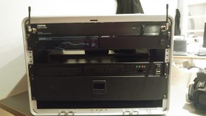
Front of rack. Missing 3 of the Radio Mic Receivers
The two (tiny) aerials on the front are connected to the antenna distribution amplifier. This acts as a buffer amplifier splitting each antenna signal 5 ways; providing a pair of antenna signals for each of the radio mic receivers and an additional output to ‘daisy chain’ into further distribution amplifiers (we will not need this).
But why have 2 independent antenna systems? Well this is all about signal path. When the system is in use the receivers don’t move about, however the radio mic transmitters do (as presenters move around, mics get handed to different people etc).  Each aerial is separated by a significant fraction of the wavelength of the carrier frequency used by the system; this means that if (when) the signal path between the transmitter and the receiver antennas is poor, due to the line of sight being blocked, weaker signals reflected off the walls ceiling and floor should still reach the antennas, however these reflected signals are the product of multiple signal paths (reflections of many different surfaces). This multi-path signal is a combination of all the received reflected signals and because the received signals will have taken paths of different lengths when combined they will be slightly out of phase meaning. By having multiple antennas a receiver is offered several observations of the same signal. Each antenna will experience a different interference environment. Thus, if one antenna is experiencing deep fade, it is likely that another has a sufficient signal. Collectively such a system can provide a much more robust link.
The Antenna distribution unit comes with a power supply large enough to power itself and 4 receivers, so it also provides 4 DC power outputs and cables to power the receivers, meaning I only have the one mains power supply for all of the radio mic system.
Below the antenna distribution amplifier there will be 4 radio mic receivers (right now there is only the one – the remaining three are on back order). Each radio mic receiver comes with enough hardware that it can be installed on its own in a rack; one small ear, and one large ear. It also comes with a link plate to join to another receiver. To fit two receivers side by side the large ear is left off and both small ears are used (one from each receiver), the two receivers are linked together with the link plates – located one on the top of the receivers and the other on the bottom (again only one is supplied with each receiver). Because I have only been sent one receiver so far I have installed this as you can see in the photo. I MUST NOT LOSE the link plate – It will be needed when I want to fit one of the 3 recivers on back order by the side of the one already in the rack. A space of 1U has been left for the other 2.
Below the radio mic receivers we have installed our OPSIS / Turbot HDMI capture system.
Finally below that Nicolas has fitted a 2U high draw. The draw has machined cut-outs so we can store and transport the 2 hand held radio mics and the 2 ‘head set’ mics and their body pack transmitters. There is even enough space to store some batteries!
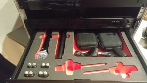
Storage for the hand held and headset mic transmitters
Now to the back of the rack…
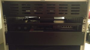
back of the rack
At the top we have fitted a 2U ventilation plate, behind the distribution amplifier and the top pair of receivers. A solid 2U blanking plate is at the bottom of the rack behind the draw.
Behind the bottom pair of radio mic receivers (the currently empty space in the picture) I have fitted a 1U short depth shelf. This proved a but of a faff because I have fitted it BEHIND the face rail so that we can still fit a 2 blanking plate to cover the remaining ‘gap’.
Onto this shelf I planed to mount the power power supply for the radio system, a small packet switch and a 4 way mains power block (to distribute power to the OPSIS, radio receivers and the ‘Wall wart’ power brick for the packet switch)
The 2U blanking plate will be cut out to house all of the plugs and sockets that need to be connected to the rack that is:
1x IEC switched & Fused power inlet
4x XLR mic sockets
1x HDMI in (from presenter laptop)
2x HDMI out (to projector and confidence screen)
4x Ethernet sockets
Each of the above will be cabled to the appropriate locations inside the rack. The HDMI input cable will also have the ‘MAGIC’ Reamere signal conditioning chip that cleans and reforms the HDMI signal enough that cheep ‘out of spec’ HDMI cables can still be used…   Who would have thaught that those cheep thin HDMI cables you buy from eBay and the likes wouldn’t be HDMI spec compliant?
Anyway the reason for going to all the trouble of fitting a cable between the equipment and a connector mounted on a backplate is two fold:
Firstly it means that we can leave connected all the buts that stay together in the rack. Nobody is going to disconnect them by mistake when unplugging the cables that go to the outside of the rack. There is a minimum number of connections presented on the back of the rack to plug into – making this much simpler to use and harder to plug into the wrong socket.
Secondly (in most importantly) it reduces damage to the kit. Someone will trip over a cable at some point, they will bend a pin, or force the wrong connector into a socket or the right connector upside down… Cables are cheep and easily replaced, so to are the connectors on the back plate, but a surface mount HDMI connector on the OPSIS or an XLR fitted to the equipment? Having “Sacrificial” connectors on the back of the unit will hopefully save us a lot of money in the long term.
Ahh that reminds me – the Power supplies on the OPSIS / Turbot in the cases we have a switch for 240 and 110 VAC so we should change them to a wide input version (as is the case for the radio receivers and the packet switch)
Something like this should be fine (we don’t need a full PC power supply – we don’t need the 3V3 rail) 1866-3987-ND.
And then a “Eurica” moment happed…
IF I put the packet switch inside the OPSIS / Turbot rack then I can also power the packet switch from the same 12V rail we power the OPSIS from. That gets rid of the nasty ‘Wall Wart’ PSU which I hadn’t yet worked out how to mount. It also means that I don’t need the 1U shelf any more. I can cable tie the Radio PSU to the ventalation pannel, and I only need to run 2 IEC power cables – one to the radio PSU and the other to the PSU in the OPSIS / Turbot case – AC power distribution is now just 2 wires sharing a ‘Spade’ connection to the Power Inlet Socket / Switch / Fuse Module.
Great problem solved – and much much cleaner / simpler than before.
And then the next problem shows up…
When we put HDMI cables on the back of the OPSIS they protrude too far out the back that they foul the back plate. So as well as needing to move the Turbot to make way for the packet switch we also need to step back the OPSIS.
First lets move the Turbot. There are a pair of disk trays in the case that are not being used in this installation. We will probably install a small SSD to replace the uSD card we are currently using for the Turbot in one, and the Turbot itself can be installed in the other. Nicolas reached for the Dremal to make some holes in one of the cages… Dremals are really not the right tool here and one broken drill bit and and hour later we decide that no they really are not the right tool here (we still don’t have the correct sized hole for the stand-offs to mount the Turbot)
There has to be a local make space round here?
Indeed there is… and they have an open meeting this evening which we are invited to attend (a talk on OpenLDAP) after which we can use the workshop. Many thanks to betz & askarel at the hsbxl Hackerspace Brussels for letting us use the your facility.
The modified OPSIS / Turbot case now looks like this:
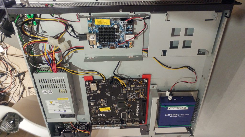
Updated chassis
The PSU still needs to be replaced (see above) but as you can see the OPSIS now sits further inside the case, we have a packet switch where the Turbot used to be and the Turbot has been moved to one of the drive bays. I have also simplified the cabling pruned back the unused wires.
Still to do (not during this sprint):
– Replace the PSU in the OPSIS / Turbot case
– Add a small SSD to the Turbot
– Source connectors for the back plate of the rack and fit
– Cable between the case and the back plate
– Add a FET to power cycle the OPSIS under GPIO control from the Turbot (Hard reset of the FPGA after reprogramming / Remote reset if things go TU during a talk)